The ER Model and ER Diagram
by K. Yue
1. Introduction to DB Modeling
- Why DB modeling?
- Many DB developers just directly figure out the relational schema without formal data modeling.
- Do you see any problem with that? Not a big problem if the problem is super simple.
- Initial ideas may be need-based. Their definitions can be very coarse and ambiguous. Real world examples:
- "I want a system to store and retrieve sale receipts for small business to claim sale tax waiver."
- "A mobile phone application to share and manage disaster recovery information."
- What are involved in DB modeling?
- Understand, capture, and refine the application requirement until it is clear and detailed enough for design and implementation.
- Communications are crucial. "Do not build your DB application. Build the DB application for the users."
- Complexity management (try to compare problem solving not involving computers). Tools and techniques:
- modeling language: Entity-Relationship Diagram (ERD) in this course.
- best practice and theory: How to model.
- process: When to do what in the modeling process.
What can you do to understand the problem and model it?
- Start by asking a lot of questions.
- Collect as much documentation as possible.
- Study and use the existing system: find out what is currently being used. Use them with the users.
- Participate in the work process.
- Model, write, and document!
- Use your own words and avoid the 'copy and paste' trap. (What is the 'copy and paste' culture?)
Some possible generic questions to ask for modeling.
- What are the purposes of the application?
- What problems will the application solve? What values will it provide?
- What are the boundary and context of the applications?
- Who are the users?
- Who are the domain experts?
- What are the available documentation?
- How does the existing system work?
- What are the workflow processes of the current system?
Two important options for database modeling:
- Entity Relationship (ER) Modeling and Extended ER (EER) Modeling: more specific to relational database.
- UML modeling: more general purpose.
Time-out Motivation:
Bureau of Labor Statistics, Computer and Information Technology Job outlook 2016 to 2026:
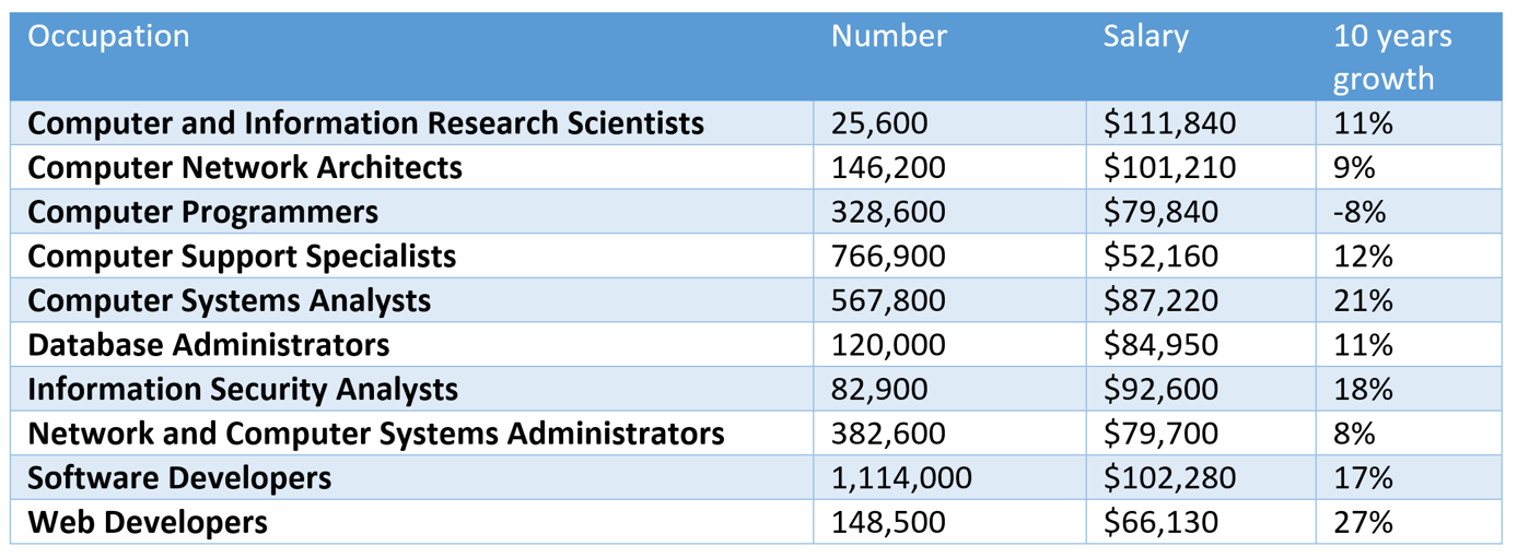
Average annual wage over all jobs in 2017: $37,600. 2016 to 2026 expected overall growth rate is 7%.
2. ER Modeling and ER Diagrams
- Some advantages of ER diagrams:
- Easy to understand
- Simple
- More specific to relational database modeling
- Good collection of theory and best practices
- Good vendor and tool support
- Good DBMS support
- Popular
- Some Disadvantages of ER diagrams:
- Limited expressiveness
- Not concise
- Can be ambiguous
- No standard: many versions that can be confusing (know your ER version).
- Mostly for relational databases only.
- There are many ER diagram tools, with different relative merits.
- For our course,
- In ER modeling, requirements are captured, such as business rules, and modeled using ER constructs.
2. ER Modeling and ER Diagrams
- Some advantages of ER diagrams:
- Easy to understand
- Simple
- More specific to relational database modeling
- Good collection of theory and best practices
- Good vendor and tool support
- Good DBMS support
- Popular
- Some Disadvantages of ER diagrams:
- Limited expressiveness
- Not concise
- Can be ambiguous
- No standards: many versions that can be confusing
- Mostly for relational database only.
- There are many ER diagram tools, with different relative merits.
- For our course, use draw.io Desktop version: er_in_drawio.pdf.
- Additional material: ER-Assistant is a simple ER tool: ("EA Assistant v2.1") from http://highered.mheducation.com/sites/0072942207/student_view0/e_r_assistant.html).
- In ER modeling, requirements are captured, such as business rules, and modeled using ER constructs.
ER Diagrams
- Entities are 'objects that exists and that can be distinguished from other objects.'
- Entities can be anything: concepts with information to store.
- Entities usually have properties that are represented by attributes.
- Note the difference between:
- Entity type: the type of an entity. E.g. the entity type Student. Compare to a class in OO modeling.
- Entity set: a set of entities of the same type. E.g. a set of entities containing students in the class CSCI 4333.1, Fall 2019.
- An entity: an instance of one entity. E.g. a student S1.
- Compare these concepts with Java's classes and objects.
- In a ER diagram, the rectangle represents an entity type that you can create an entity instance to be stored in an entity set.
- Relationships are associations between entities.
Traditional ER notation (Chen's Notation)
- Symbols used in traditional ER Diagrams:
- Entity: rectangle
- Relationship: diamond
- Attribute: oval
- Other symbols used in traditional ER diagrams:
- Double rectangle: weak entities (existence depending on parent entities)
- Double diamond: relationship joining a weak entity to its parent entity.
- Double oval: multi-valued attributes.
- Dashed oval: derived attributes.
- Cardinality (or multiplicity): 1 for one, N for many.
Crow-Foot Notations
- Entity has a compartment for storing attributes.
- Binary association does not need to use a diamond.
- Cardinality: crow-foot. 0, |, ∈ for zero, one and many.
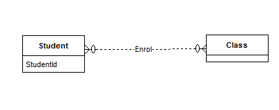
Example:
Description: A student has a unique student id and can enroll in any number of classes.
For example, Jane Smith, with an student of 3100910, enrolls in the classes 'CSCI 4333.1' and 'CSCI 3352.1'.
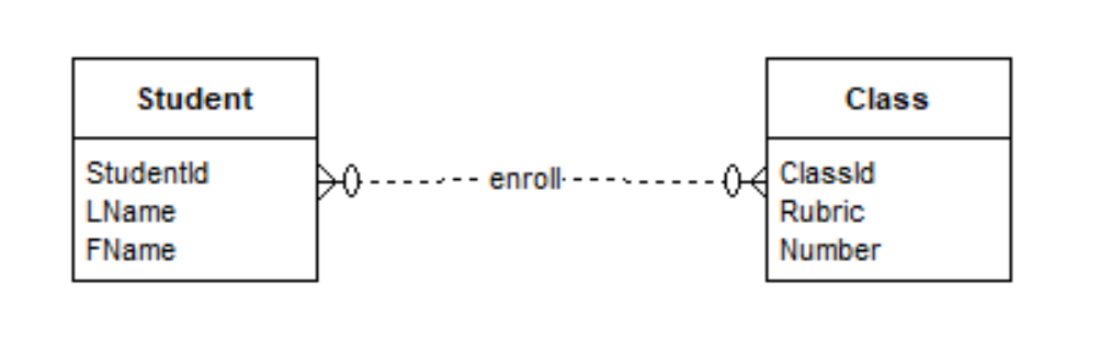
ER Modeling is about capturing requirements by ER model. In this example, the assumptions made by the requirements are:
- There are students with StudentId, LName and FName.
- There are classes with ClassId, Rubric and Number.
- A student can enroll in 0 or more classes.
- A class can have 0 or more students enrolled in it.
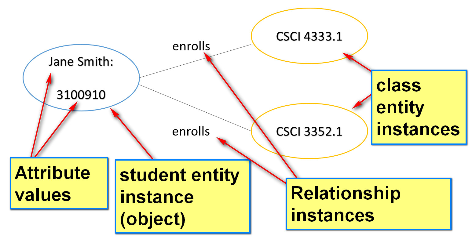
The ER diagram can be used to create entity and relationship instances.
- Note the difference between:
- Entity type: the type of an entity. E.g. student, class
- Entity set: a set of entities of the same type. E.g. a set of entities containing students in the class CSCI 4333.1, Spring 2020.
- An entity: an instance of one entity. E.g. the student S1, the class CSCI 4333.1.
- Compare these concepts with Java's classes and objects.
- In a ER diagram, the rectangle may represent an entity type that you can create an entity instance to be stored in an entity set.
Entity type: Student(StudentId, LName, FName)
Entity (instance): (3100910, 'Smith', 'Jane')
Entity set: {(3100910, 'Smith', 'Jane'), (2001001, 'Johnson', 'John'), (1201021, 'Bajaj', 'Rashid')}
Example:
Consider again:
Note:
- We will demonstrate how to draw the ER diagram in draw.io and/or ER Assistant in class.
- It does not use the traditional ER notations,.
Student is an entity type that you can use to instantiate Student objects (entity instances). Examples: we may have the following instances.
S1: Sadegh Davari
S2: Brad Pitts
S3: Stephen Curry
Each student entity represents a student.
Class is an entity type that you can use to instantiate Class entity. Examples: we may have the following instances.
C1: CSCI 4333
C2: CSCI 3388
C3: CINF 3311
Each course entity represents a course.
The relationship Enroll represents association between a student (instance) and a class (instance). The meaning: a student may enroll in a class. For example, we may have:
S1 enrolls in C1
S1 enrolls in C3
S2 enrolls in C1
S3 enrolls in C2
S3 enrolls in C3
The relationship is actually not between two entity types. The relationship is between two entity instances of some types.
In fact, a relationship may be between two entities of the same type.
Example:
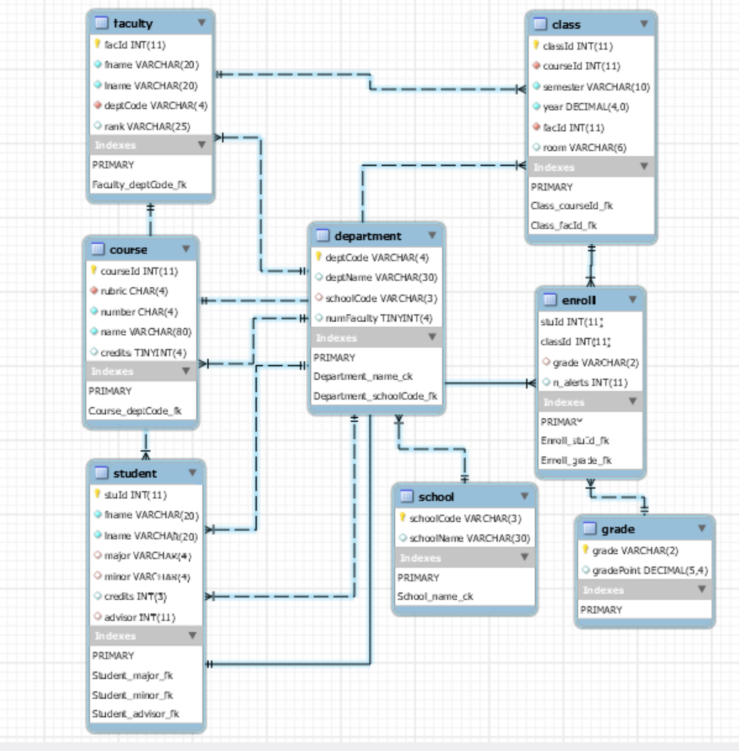
Toyu: A drastically simplified university.
ER Diagram (drawn using MySQL Workbench)
Example:
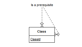
Consider:
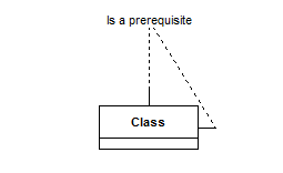
The meaning of the relationship "is a prerequisite": one class entity can be a prerequisite of another class entity. For example, we may have:
C1 is a prerequisite of C2
C3 is a prerequisite of C2
- An attribute presents a property of an entity.
- A multi-valued attribute may have many values.
- The name of a multi-valued attribute is usually in plural.
- Example: Hobbies, Names, Honors, Medals, etc.
- Example: Names: a DB problem may need to store all names (or alias) of a person. 'Bun', 'Bun Yue', 'K.B. Yue', etc.
- A derived attribute has a value that can be computed (derived) from other attributes (that may be in another relations).
- In the traditional ER model:
- ordinary attribute: oval.
- multi-valued attribute: double oval
- derived attribute: dashed oval
- Draw.Io or ER Assistant does not directly support notations for multi-valued attribute or derived attribute.
- Multi-valued attributes: consider promoting the attribute to an entity.
- Derived attributes: document them in the comment section.
- Relationships are connections, associations, or interactions between entity instances.
- Note the difference between:
- relationship type: what entities and their types participate in the relationship.
- relationship set: a set of relationships of a specific type
- relationship instance: a relationship between two entity instances.
Example:
Consider again:
The relationship type Enroll allows a student entity to has an Enroll association with a class entity.
Here are five relationship instances of Enroll:
r1: S1 enrolls in C1
r2: S1 enrolls in C3
r3: S2 enrolls in C1
r4: S3 enrolls in C2
r5: S3 enrolls in C3
Together, they form a relationship set.
- There are different degree of relationship
- binary – links two entities
- ternary – links three entities sets
- N-ary – links n entities
- EA-Assistant only supports binary relationship.
- Relationship cardinality (or multiplicity): number of entity instances to which another entity can form under the relationship.
- For binary relationship:
- one to one
- one to many
- many to many
- For ternary relationship, the cardinality cannot be drawn in Crow's Foot notation.
- A ternary relationship may be replaced by
- two binary relationships: e.g. Figure 3.8.
- an entity and three binary relationships, e.g. project assignment between employee, project and role.
- In general, avoid n-ary relationship, where n>2.
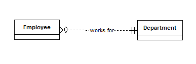
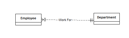
Example:
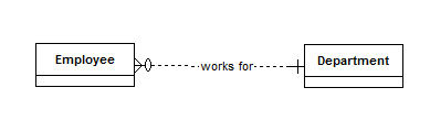
- Zero or many employees work for one one department.
- Assumptions:
- A department may have no employee.
- An employee must work for one department.
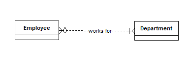
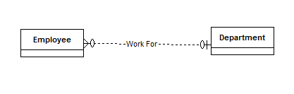
- Zero or many employees work for one and only one department.
- Assumptions:
- A department may have no employee.
- An employee must work with exactly one department. if an employee does not work for any department, it cannot be added to the database.
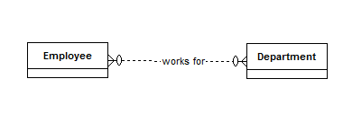
- What are the assumptions made below?
Example:
Discuss the ER model for students in an university and its relationship with degree programs (e.g. B.Sc. in CIS, BA in Math, MS in CS, etc).
You may start with:
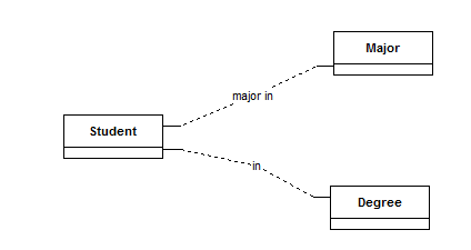
- What should the cardinality be?
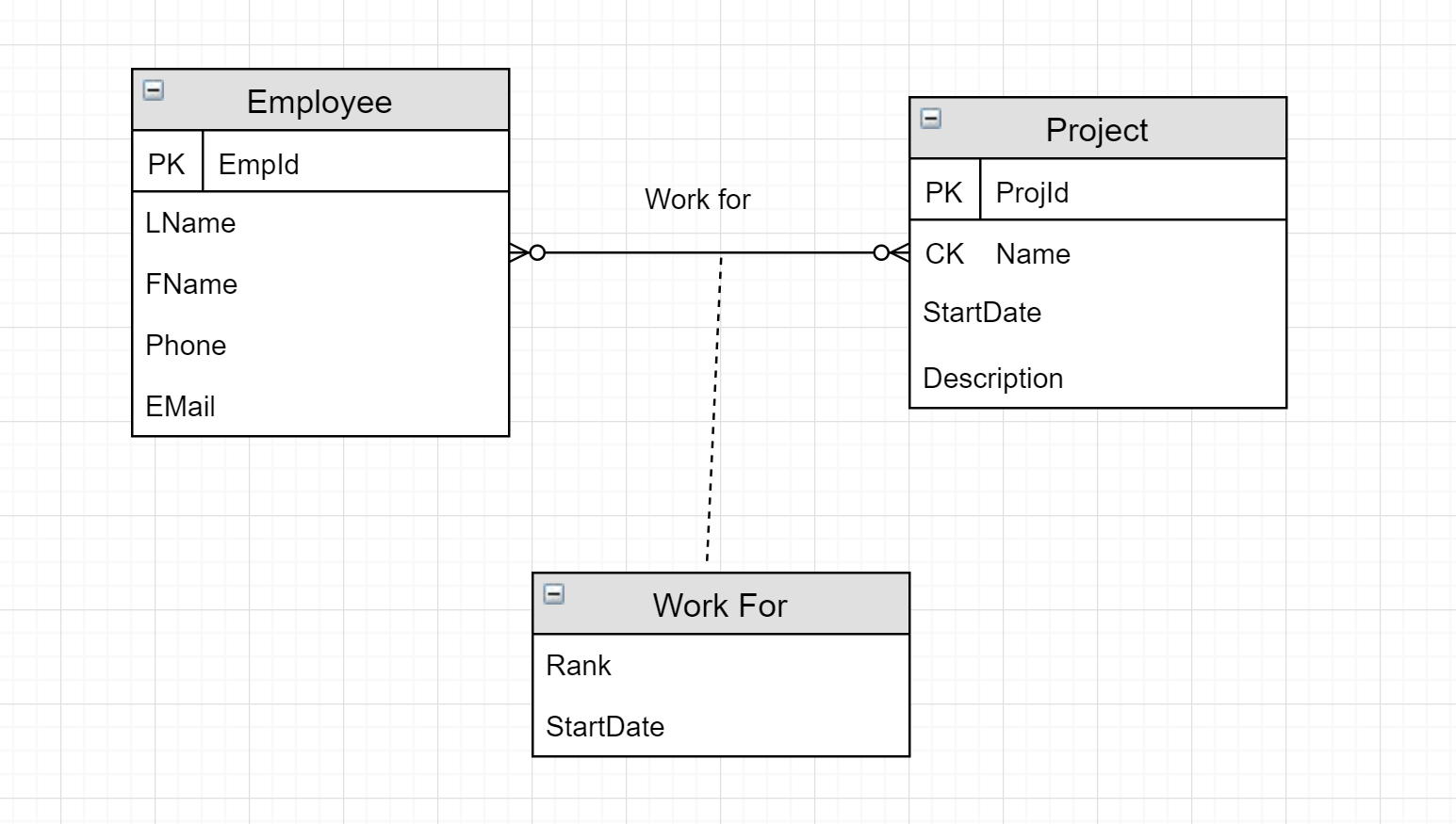
- Relationship may have entity role: how the entity participate in the relationship.
- Roles are not supported by EA-Assistant.
Example: in Draw.io
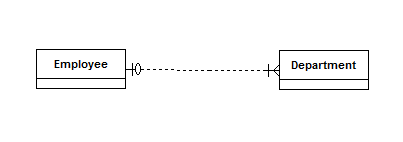
- Kind of participation:
- Total participation
- Every entity must participate in the relationship.
- Represented by double line from entity rectangle to relationship diamond in some notations.
- Recommend not to use (2).
- Partial participation
- An entity instance may or may not participate in the relationship.
- Note that this classification can be captured by the multiplicity of the relationship:
- Total participation: 0 not allowed (1..1 or 1..*)
- Partial participation: 0 allowed (0..1 or 0..*
Total participation:
Partial participation:
- Other relevant concepts are listed below.
- Existence dependence: same as total participation, but more forceful. Example:
- If an employee must work for a department, this is total participation.
- It can also be interpreted as "existence dependent": an employee cannot exist (in the database) without a department.
- Semantically, in the real world, employee can exist independent of a department. It may just not exist in the database.
- If Y is existence dependent of X, and Y does not have its own identifiers, then Y is a weak entity and X is a strong entity.
- Weak entity may have a partial key, a discriminator, that unique identifies a weak entity among those related to the same strong entity.
- In some notations, use double rectangle for weak entity, with double diamond for relationship connecting it to its strong entity (e.g. Ricardo).
- Recommendation: don't use it. This is because an entity can be a weak entity in one relationship and a strong entity in another relationship.
Modeling is about finding the true meanings, assumptions, and requirements and captured them in the selected modeling language.
- There is no 'mechanical formula'.
Example: Chen's suggested 'rule of thumb':
- Person -> Entity type
- Bun -> Entity (instance)
- Student -> Entity type
- Jean (a student): Entity
- Teaches (as in Bun teaches Jean): Relationship type
- Black-eyed: values of an attribute type.
- 'Black' eye: attribute for entity.
However, there are so many exceptions.
Example:
Figure 3.11 and Figure 3.12 of Ricardo.
Notes:
- Do not confuse an ER diagram with a relationship diagram (usually provided by DBMS).
- A relationship diagram shows the relations in a database and their relationships through foreign keys.
Example:
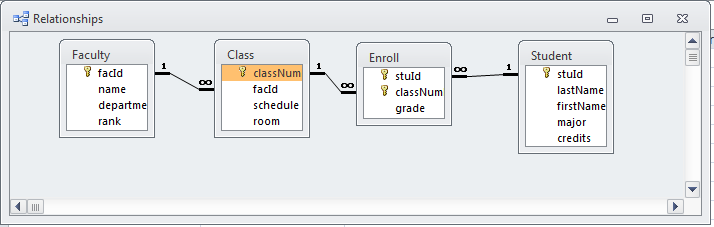
Note that:
| |
Entity-Relationship Diagram |
Relationship Diagram |
| Rectangle |
Entity |
Relation |
| Link |
Relationship between entities; can be n-ary. |
Foreign key relationship between two relations; always binary. |