Introduction to UML
by K. Yue
1. Introduction to UML
- UML: A set of graphical notations for object-oriented modeling.
- Wikipedia: "The Unified Modeling Language (UML) offers a way to visualize a system's architectural blueprints in a diagram."
- A standard maintained by OMG: OMG's UML page.
- Two major versions:
- Version 1.4.2: international standard released in 2005.
- Version 2.5.1: released in 2017, added nested classifiers and improved behavior models. Specification: https://www.omg.org/spec/UML
- Two main types of diagrams:
- Structure diagrams: model static structures.
- Behavior diagrams:model dynamic behaviors.
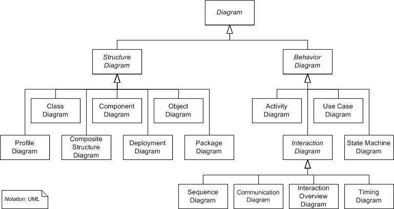
- Version 2.5 has 15 diagrams: 7 structure diagrams and 8 behavior diagrams.
- Some Resources:
- We will focus on the class diagram only.
Class Diagram of UML 2.2 diagram (from Wikipedia):
2. Class Diagrams (Emphasis on DB applications)
2.1 Introduction:
- A static structure diagram in UML.
- "Describes the structure of a system by showing the system's classes, their attributes, operations (or methods), and the relationships among the classes." -- from Wikipedia.
- Read "class diagram" from Wikipedia: http://en.wikipedia.org/wiki/Class_diagram.
- For a significantly better introduction by IBM: http://www.ibm.com/developerworks/rational/library/content/RationalEdge/sep04/bell/.
- Two kinds of tools for drawing UML diagrams:
- Graphical tools: main purposes are drawing diagrams (e.g., MS Visio, draw io, etc.)
- Computer-Aided Software Engineering (CASE) tools: for software development with some understanding of the semantics of diagram elements (e.g., MagicDraw, IBM Rational Rhapsody, Visual Paradigm, Astah, etc.)
- We use Astah UML Editor
- We will use community version in classroom demonstration, which is now deprecated.
- Students can use the more powerful student version for free: search "astah student license".
- One may also use UML object diagrams to show objects and their associations of a snapshot of the system.
2.2 A Simple Conceptual Modeling Process
- Examine application requirements to gain a good understanding of the problem.
- Conduct an analysis to extract concepts that may have data requirements.
- For each concept, design how should it be modeled? Major options are:
- by attributes
- by a class
- by associations between classes (including special associations, such as composition, aggregation, generalization, etc.)
- no need to model (as it does not represent data requirement)
These steps are repeated until the model reaches the necessary fidelity, accuracy, and precision.
Example:
Problem. A used car dealership application's subsystem: information about cars and their manufacturers.
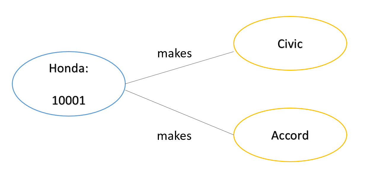
Specification description: A car manufacturer has an unique id and name. A car maker may make many cars. For example, Honda, which may have an manufacturer id of 10001, makes Civic and Accord.
Analysis and Design
Some observations:
- Manufacturer: a class (template) that can be used to initiate many manufacturer objects (instances).
- Honda: an object of the class Manufacturer.
- Resolve ambiguous terms: e.g., the term "manufacturer" may refer to the manufacturer class, or a particular manufacturer (a manufacturer object such as Honda).
- Define synonym: manufacturer, car manufacturer, car maker. Different terms can refer to the same concept.
- "Unique id": may be modeled as an attribute (name), a property of the manufacturer class.
- Make additional assumptions: Every manufacturer object must have an unique id.
- 10001: attribute (value) of the id of a manufacturer object.
- Name: a property of a manufacturer.
- Additional assumption: Every manufacturer object must have a name.
- Car: a class, as there may be many brands of cars.
- Prepare questions: Do we need to introduce the concept model (e.g., Coupe, Sedan, Si Coupe)?
- Civic and Accord: object instances of Car.
- Additional assumption: Every car must have a name as its attribute.
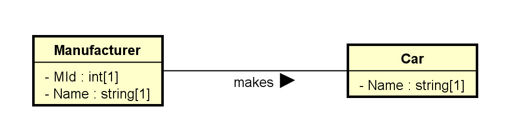
- Make, or manufacture: a relationship between a manufacturer (object) and a car (object).
Class Diagram:
Object Diagram:
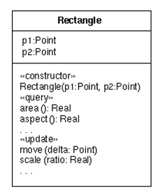
2.3 Classes
- Drawn as a rectangular box.
- The class names, attributes, and operations may be specified, with selected details in the name, attribute, and operation compartments respectively.
- Attribute and operation compartments are optional.
- For DB modeling, the attribute compartment will eventually need to be clearly modeled. The operation compartments may not be needed.
- The levels of details depend on the phases of modeling. It is a common mistake to specify too much detail in the early modeling phases.
- As modeling proceeds, more details are added, updated, and refined.
Note that software application modeling and database modeling has different focus.
- Software modeling: focus on operations (methods, especially public methods).
- Database modeling: focus on attributes (data).
Example: The following sequence of diagrams of how the modeling of the used car dealership application may proceed.
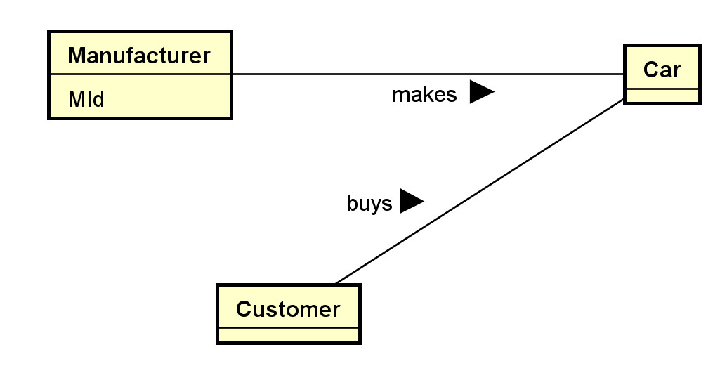
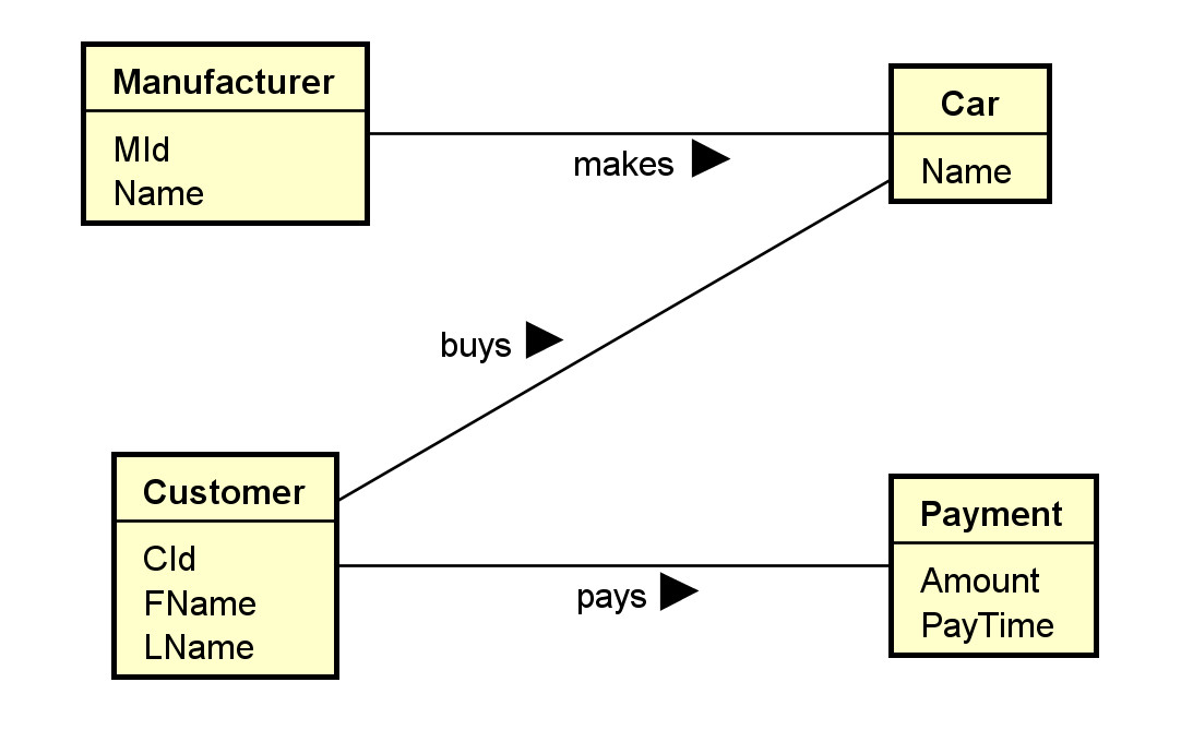
Initial version: v0.0.1.0:
- Only some major classes, associations, and attributes.
Version v0.0.1.1:
- Add a payment class and some attributes.
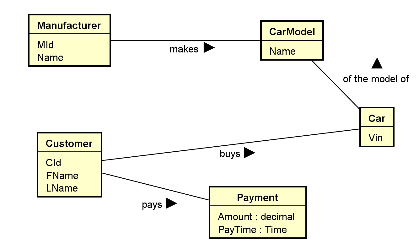
Version v0.0.1.2:
- Decided to split the concept 'car' into two concepts 'car model' and 'car'. Adjust associations.
- Add some type information.
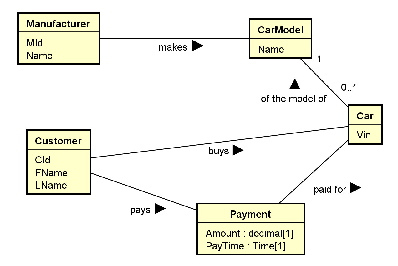
Version v0.0.1.3:
- Add an association between Payment and Car.
- Add multiplicity of the association "of the model of":
- A car must be made of one car model.
- There may be many cars made of the same model.
- Add multiplicity of 1 to the attributes Amount and PayTime of the class Payment. They are mandatory.
- For example, one may focus on the main classes and their associations in the first model, without worrying about the attribute or operation compartments.
- Most UML editors allow controlling visibility of different elements. For example, in Astah:
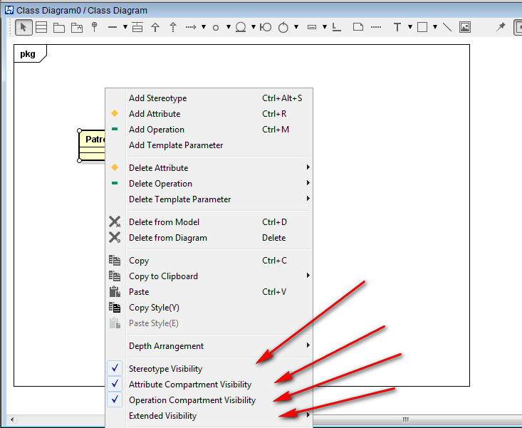
- A stereotype (specifying the kind of entities) and a property list with tagged values can be added to any compartment.
- Their flexibility allows for customization and extensibility to fit specific applications.
- Additional properties on data members may be specified, such as:
- Visibility: + (public: +, protected: #, private: -, etc.)
- data types
- abstract (in italic) or concrete (as constraints)
- class members (underscored) or instance members
- default values
Example: for software modeling:
Example: for database modeling.
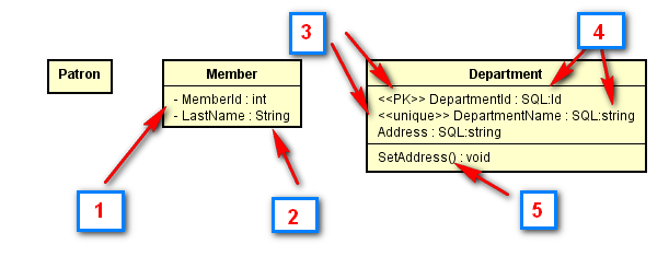
The class Patron may be identified in the first draft of the UML class diagram.
- In a subsequent iteration, attributes may be added using settings of the UML tool showing visibility of the attribute members.
- Data types may be included using predefined data types provided by the tool.
- In a further iteration, stereotype may be added, such as to identify the primary key <<PK>> and simple candidate key <<unique>>.
- More specific user-defined types (or implementation types) may be used.
- Operation members may be added. They are in general less important than data members in data modeling.
- Multiplicity should eventually be added, as shown in the diagram below.
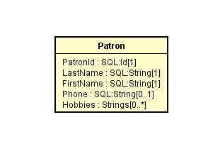
- Note that multiplicity can be used to depict nullability and multi-valued attributes. In this example, PatronId is not nullable ([1]), Phone is nullable ([0..1]) and Hobbies can have multiple values ([0..*]).
Check out the introductions to class diagrams from agile modeling and wikipedia.
- Some possible relational database extensions on attributes may include:
- Multi-valued: * or by using multiplicity.
- Multiplicity can also be used to indicate whether an attribute is nullable.
- Derived: <<derived>> using stereotype, \, or using other specific notation
- Primary key: <<PK>> as stereotype.
- Candidate keys: <<CK>> as stereotype.
- Unique field: <<unique>> as stereotype.
- Nullability: <<nullable>> or by using multiplicity.
- User-defined or system defined SQL data types.
- Indexing: <<index>> as stereotype.
- Check with your organizations for UML guidelines on a specific project.
- An example of a database profile for UML: http://www.agiledata.org/essays/umlDataModelingProfile.html
- may be adapted for uses in later phase of modeling.
More Properties of Classes
- A class is a 'first-class citizen.'
- It has attributes.
- It can form associations with other classes.
- Objects of a class can exist by themselves.
- It has more structures for modeling data requirements.
- As a comparison, an attribute is not a first-class citizen.
- It does not have sub-attributes.
- It cannot form associations with other elements.
- The existence of an attribute depends on the object..
- Objects can be instantiated from classes.
Example:
We may have four objects of the student class: S1, S2, S3 and S4. Each student object represents an individual student in a database application.
We may have three objects of the course class: C1, C2, and C3. Each course object represents an individual course in the database application.
2.4 Associations
- Binary associations are represented by solid lines.
- Important options include:
- Association names with directional arrows (for reading).
- Association roles: the role of an object participating in an association.
- Multiplicities: the allowed number of associated objects.
- Association attributes can usually stored by promoting an association to an association classes.
- Qualifiers: association attributes to partition the targeted classes.
- Navigational requirement: specified by arrows. Usually not used in data modeling.
- Dependency constraints: by dotted lines.
- Some modeling questions and decisions:
- Should we model something as a class or as an association?
- Should we model something as a class or as an attribute?
- What kind of association should I use? Binary association, association class, n-ary association?
Example: Note that no attribute is shown in this initial phase.
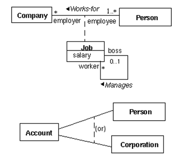
Note:
- Job is an association class.
- The arrow in the association "works-for" shows the direction of the association.
- The association "manages" is between two job objects.
- The {or} designation specifies the partition of the account class into two classes: person (account) and corporate (account).
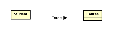
Example: For:
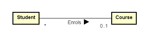
The association Enroll describes the association 'type'. An association is actually between two objects (a student object and a course object). Examples:
S1 -- C1: meaning student S1 is enrolled in course C1.
S1 -- C3: (The associations S1--C2 and S1-C4 do not exist. This means the student S1 has not enrolled in the C2 or C4.)
S2 -- C1
S2 -- C2
S2 -- C4
S3 -- C3
S4 -- C1
S4 -- C4
2.5 Multiplicity
- Multiplicity can be specified by a number, the symbol * (many), a range, or a set. Some example:
- 0..1: zero or 1
- 1..1: only 1
- 1: may be 0..1 or 1..1; usually interpreted as 1..1
- 0..*: zero or many
- 1..*: 1 or many
- *: many; may be 0..* or 1..*
- 1..4: 1 to 4
- {1, 2, 6}: 1, 2 or 6
- {1, 3:5, 7:9}: 1, 3, 4, 5, 7, 8, 9
- Multiplicity is a very common source of errors. Please refer to the explanation of the following diagram until you are very clear about it.
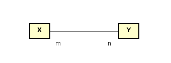
- Meaning:
- Every X object must be associated with n Y objects.
- Every Y object must be associated with m X objects.
Example
What do you think about these class diagrams?
(a)
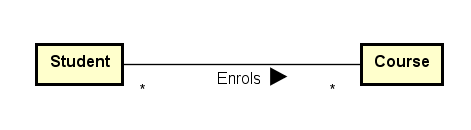
Assumptions made:
- A student may take many courses.
- Not sure whether a student is allowed to take zero course since * (instead of 0..* or 1..* is used).
- A course may have many students enrolled.
- Not sure whether a course has no student enrolled since * (instead of 0..* or 1..* is used).
(b)
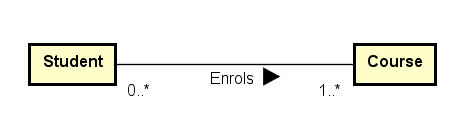
Assumptions made:
- A student must be enrolled in one or more courses (may not be a reasonable assumption).
- A course may have 0 or more students enrolled.
(c)
Assumptions made:
- A student can only be enrolled in 0 or 1 course only (sound not reasonable).
- A course may have many students enrolled.
- Not sure whether a course has no student enrolled since * (instead of 0..* or 1..* is used).
Aggregation indicator
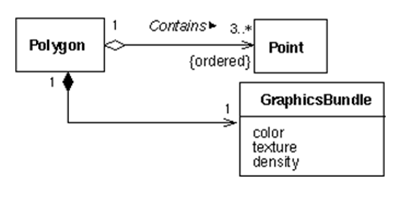
- aggregation (hollow diamond) and composition indicator (solid diamond):
- Aggregation models the ‘a-part-of’ relationship (whole-part). E.g., car-wheel.
- Composition is a strong form of aggregation: the part's lifecycle is dependent on the whole's lifecycle; e.g. university-department, building-room.
- They can also be represented by using multiplicity.
Example: Aggregation and Composition
What do you think about this composition and aggregation examples in: http://en.wikipedia.org/wiki/File:Congregationalism?
Ternary Associations
- N-ary associations are represented using a diamond connecting to participating classes.
- Not so common.
- May be modeled as a class instead.
- A ternary association involves three participating objects.
An example from a tutorial:
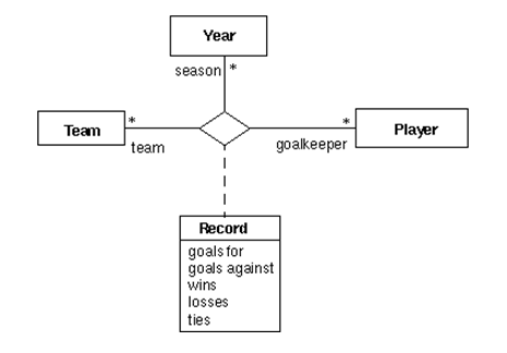
Notes:
- In modeling, a ternary association can reasonably be replaced by a number of binary associations.
- Don't use n-ary associations where n>=3 unless you are sure.
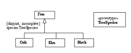
Generalization and Specialization
- Generalization is represented by a hollow triangle at the superclass.
- Generalization models the 'a-kind-of’ association.
- It is mainly used to
- manage classes with common data members and methods by put these common members into their superclass.
- provide inheritance.
- avoid multiple copies of member definition.
- Some options of generalization includes:
- discriminator (the name of the partition),
- powertype (a class in which an instance of it is a subclass of the superclass),
- constraints (overlapping, disjoint, complete, incomplete and user defined constraints).
Example:
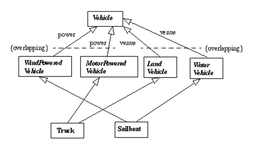
- There are many possible options and extensions.
Constructing class diagrams: some tips
- There are many methodologies and best practice tips to construct effective class diagrams.
- There are many possible modeling options: e.g., classes versus attributes, classes versus associations, multiplicity, etc.
- Need to fully understand the assumptions and implications when making modeling decisions.
- Do not model implementation details in earlier modeling phases.
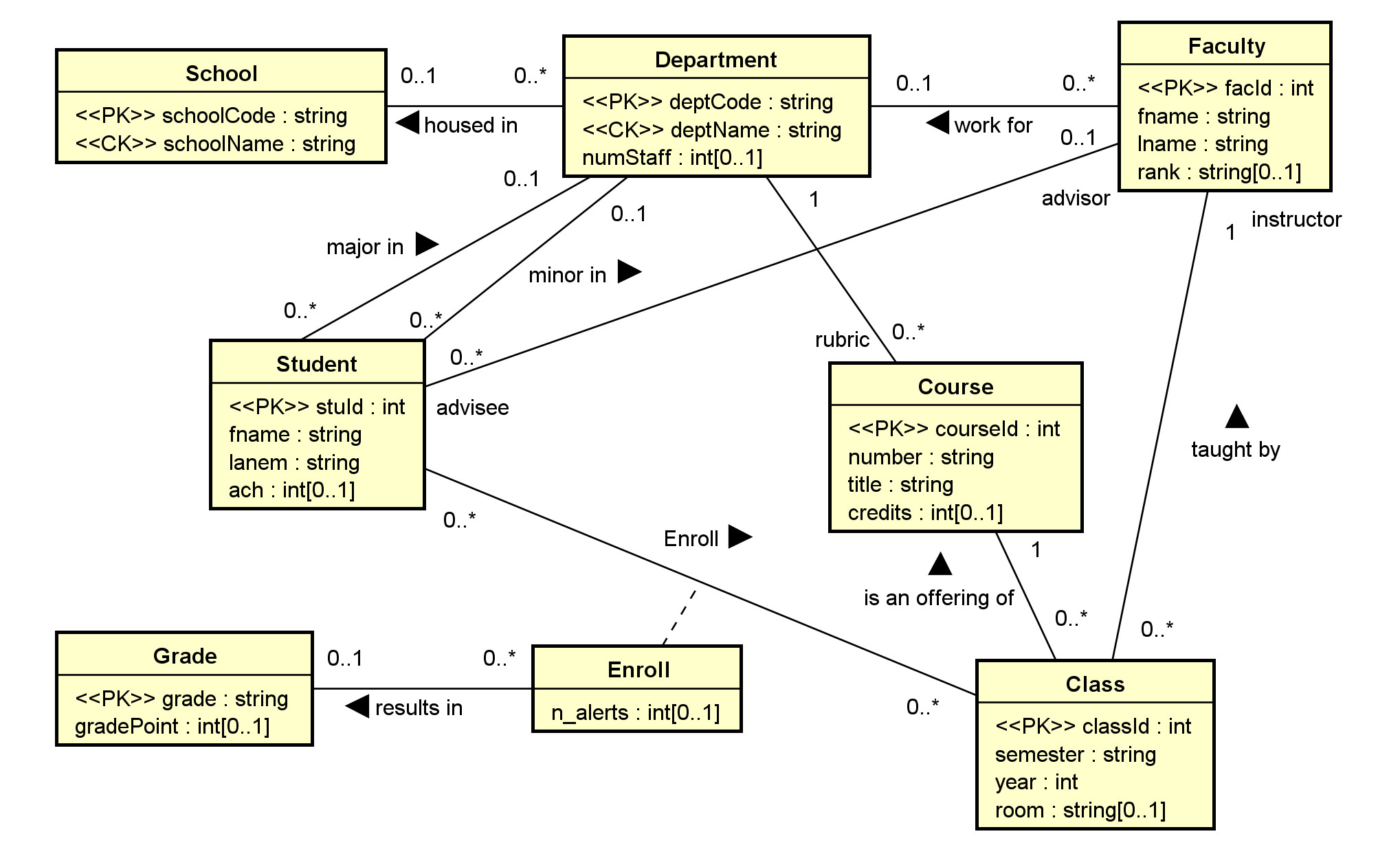
3. Example: toyu
A reasonable conceptual model of the toyu database in UML: